Parallel I/O port programming example
Source: Solution Development Department Date: 2020-11-25
| The most typical application of single chip microcomputer I/O is to form a display circuit through the I/O port and 7-segment LED digital tube. We start from the commonly used LED display principle and explain in detail the circuit and programming principle of using the single-chip microcomputer to drive the LED digital tube. , The purpose is to let beginners understand the programming principle of I/O port through this programming paradigm, which is intended to draw inferences from one another. The light-emitting principle of LED is very clear to those with a little electronic technology basis. We don’t want to introduce too much. The 7-segment LED digital tube uses a single piece of insulating material in a certain shape. The LEDs are arranged in a combination of “8” nixie tubes, and their electrodes are drawn out, and the corresponding dots and strokes are lit to display the numbers 0-9. |
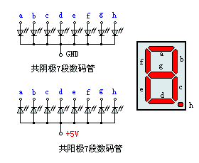
LED digital tubes are divided into common cathode and common anode according to the different connection methods of LEDs. Understanding these characteristics of LEDs is very important for programming, because different types of digital tubes, in addition to their In addition to differences in hardware circuits, programming methods are also different. The picture on the right is the internal circuit of the common cathode and common anode digital tubes. Their light-emitting principle is the same, but their power polarity is different. Connecting the cathodes of multiple LEDs together is a common cathode type, and connecting the anodes of multiple LEDs together is a common anode type. Take the common cathode type as an example. If the cathode is grounded and the anode of the corresponding section is connected to a positive power source, the section will emit light. Of course, the current of the LED is usually small, and it is generally necessary to connect a high-current resistance in the loop. If we connect the "b" and "c" segments to the positive power supply, and the other ends are grounded or left in the air, then the "b" and "c" segments will light up. At this time, the digital tube display will display the number “1” . And connect the "a", "b", "d", "e" and "g" segments to the positive power supply, and the other pins are left floating, and the digital tube will display “2”. The display principle of other characters is similar, and readers can analyze it by themselves. |
 |
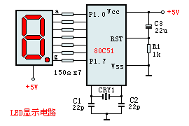 |
The left picture is the experimental circuit diagram. We use 80C51 single-chip microcomputer, and capacitors C1, C2 and CRY1 form the clock oscillation circuit. This part basically does not need to be debugged. As long as the components are reliable, it will start to vibrate normally. C3 and R1 are the reset circuits of the single chip microcomputer. The parallel ports P1.0-P1.7 of the 80C51 are directly connected to the "a-f" pins of the LED digital tube, and the indirect current limiting resistors R3-R10 are in the middle. It is worth mentioning that the output drive current of the 80C51 parallel port is not very large. In order to make the LED have sufficient brightness, the LED digital tube should use high-brightness devices. In addition, the 80C51 in the picture can also be used with other single-chip microcomputers of the C51 series, as long as their instruction system is compatible with C51, they can run normally, and the program can be directly transplanted, such as low-cost Flash type AT89C1051 or 2051 (Detailed technical manual) etc. Their ROM can be repeatedly erased and written, which is very suitable for experimental purposes. △ Program list: |
Recommended news

ELAN: Capacitive multi-finger touch technology
Di Guanjie: Breaking through technical barriers and leading the innovation and development of MCU field

IC factory ELAN Group joins hands with NTU AI Center to create intelligent transportation system to enter Southeast Asian countries

NY2 series products are single-chip CMOS music and speech synthesis ICs
