Programming Skills of EH78 Series MCU
Common reference books on the market that introduce the EM78 series give some application examples, but these examples generally have a small amount of program code and single functions. Although these examples do play a good role for novices, a product may have very complex functions and the program may reach several thousand lines, which will cause some problems that are not encountered in short programs. Taking the author's development as an example, the program has more than 5,000 lines in total, and the effective assembly code has more than 3,000 lines. Since ELAN does not provide a C compiler environment, it can only be coded in assembly. The structure and organization of assembly are not very clear compared with C language. Coupled with the uniqueness of the EM78 microcontroller structure, when the program code is large There will always be some new problems. The following summarizes the problems encountered in practice and their solutions for reference.
1 How to read RAM data
EM78 series RAM can be regarded as RAM in ordinary single-chip microcomputers, or as registers (general and special registers). Take EM78P447 as an example, RAM has a total of 148× 8 bits, and its structure is shown in Figure 1.
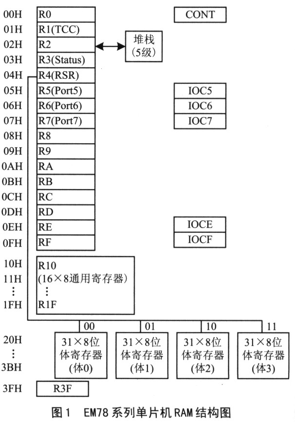
The address is 20H-3EH, there are 124 (31×4) in total, distributed in 4 RAM“body”(Bank). The 4 individuals are respectively labeled as “BankO(body O)”, “Bankl(body1)”, “Bank2(body2)”, “Bank3(body3)”. When there are not many variables used in the program or the amount of data is not very large, this RAM structure will not have any impact on the program, that is, program variables can be allocated in a Bank; but when there are many variables, the operation will be somewhat Troublesome, and at the same time, it may cause program errors due to improper Bank selection in the program. The author thinks that when the amount of data is large, as long as the data is operated, the bank selection must be carried out first. Especially for subroutines, bank selection is required as soon as you enter the subroutine, so as to control the range of data to be operated, and always know which bank the data you operate on is in. By changing the "body selection code", that is, the highest 2 bits of the RSR register, select the data bank to be accessed. A program is given below to illustrate.
BS RSR, 7: to Bank2
MOV A, 0X2F
AND A, @OB00111111
MOV OX2E, A
CALL LCD _LEAR; call the display screen reset program
LCD CLEAR:
BC RSR, 7; to Bank0
BC RSR, 6
MOVA, @OB00000000
MOV LCd address, A
……
As shown in the above program, the Bank2 data area is visited before LCD_CLEAR is called, and then the LCD-CLEAR subroutine is called. At this time, in the subroutine, if you do not pay attention to the bank problem of the data, that is, if you do not set to select BankO, then the data operation to BankO will occur on the corresponding data address of Bank2, and an error occurs in the program. Therefore, after entering the subroutine, immediately select the bank where the data is to be used to prevent misoperation. The development language of the EM78 series single-chip microcomputer is assembly language. Therefore, when writing assembly programs, you must develop a good programming habit, which is very beneficial Program development and maintenance. The author recommends the following operations for variables in the program.
①Define the variable table. Define the variable table at the beginning of the program, name each variable, and allocate address space.
②It is better to define related variables in the same Bank, so that when operating on these related variables, you can avoid the trouble of choosing Bank.
③Operate with variable names. Do not directly manipulate the address of the variable, it is better to operate with the variable name, so that when the variable needs to change the name or the assigned address needs to be changed, the variable table can be directly changed without changing the specific program. This is very beneficial for larger programs, not only can increase the readability of the program, but more importantly, improve the convenience and maintainability of the program.
The above points are very important for writing high-quality code and should be carefully understood in specific practice.
2 Program cross-page jump and cross-page calling skills
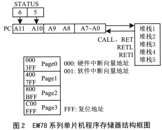
First, we need to introduce the ROM structure of the program memory of the EM 78 series single-chip microcomputer. The program memory ROM capacity of the EM78 series is 4K×13 bits, and the Page (“page”) allocation principle is adopted, which is to divide the 4K program space into 4 pages, each with a page capacity of 1K. Its structure is shown in Figure 2, where Page0 (000H ~ 3FFH), Pagel (400H ~ 7FFH), Page2 (800H ~ BFFH), Page3 (COOH ~ FFFH). The two long-distance jump instructions in the instruction system, JMP and CALL, carry only 10 bits of address code, 210=lK address space, that is, only jump in 1K space. When using the JMP instruction, load the target address to the lower 10 bits of the PC program pointer; when using the CALL instruction, load the target address to the lower 10 bits of the PC program pointer, and PC+1 is pushed onto the stack, calling the same 1K page Any program. The PC program pointer (register R2) and the number of stacks are 12 bits, that is, the addressing space is 4K, and a program page is 1K. Page selection is done by setting Bit6 (PS1) and Bit5 (PSO) of the status register R3.
In EM447, when you need to jump or call a subroutine on a different page, you need to modify the PSl and PS0 of R3 before calling, so that the status will be changed when the IMP instruction or CALL instruction is executed The PS1 and PS0 of the register R3 are loaded into the A11 and A10 of the PC, so the PC program pointer can jump freely in the address space of the 4K range.
When writing a large amount of program code (more than 1K), the program cross-page jump and cross-page call are unavoidable. When using the JMP instruction, you must know which page you will jump to; when using the CALL instruction, you must know which page the subroutine you want to call is located in. In this way, before using the JMP instruction and the CALL instruction, the PS1 and PS0 bits must be set to select the storage space that will jump or call the program. The routine is as follows:
BS STATUS, PSl; go to Page3
BS STATUS, PS0
CALL INIT CLEAR; call the initial data clearing program
CALL SYS INIT; call system initialization program
BC STATUS, PSI; to Pagel
JMP SYS_BEGIN; jump to the system startup program
In the routine, first set the corresponding bit of PS to select Page3, then call INIT_CLEAR and SYS_INIT, then select Pagel, and jump to the SYS BEGIN main program in Pagel. For larger programs, such calls and jumps often occur, so you must be familiar with the allocation of program address space before writing programs.
3 Principles of ROM modular programming
Because the debugging environment provided by ELAN only supports assembly language, and the program written in assembly language is inferior to the program written in C in structure and order, so when writing the program, you should use the subroutine function as much as possible Modularization means writing subroutines to complete a certain function, so that the structure is clear and the call is convenient.
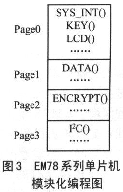
When the author is writing the program, according to the Page structure of the EM78 series single-chip microcomputer ROM, the subroutines are stored in different pages according to the principle of distinguishing function. As shown in Figure 3, the memory space allocation of the program in the author's project .
In Figure 3, PageO mainly stores commonly used subroutines, such as system initialization, keyboard scanning, liquid crystal display, etc.; Pagel stores some data processing programs, such as data copies of different banks. The hexadecimal is converted to binary compression BCD code and other programs; the encryption algorithm program stored in Page2 is the most important part of the author’s project development, so it is placed in a separate Page; Page3 is mainly for reading and writing IC memory 24LC02 Operation subroutine. In this way, the subprograms with similar functions are placed in a Page, so that the program storage space is divided according to the structural characteristics of the single-chip microcomputer and the actual development of the project. When debugging in this way, it is easy to find the area where the problem occurs, making the program structure clear, easy to call, and easy to debug and maintain.
4 Using partition instruction redundancy technology to improve software anti-interference
In order to ensure the stable and reliable operation of the program, sometimes software and hardware anti-interference design must be adopted. In some venues, although a large number of interference sources will not cause damage to the single-chip hardware system, they often destroy the timing of digital signals, change the contents of the single-chip registers, and cause the program to "run away" or enter an endless loop. Therefore, on the basis of improving hardware reliability, it is also necessary to adopt software anti-interference in program design, so as to improve the reliability of software, reduce the occurrence of software errors or still enable the system in the case of errors.
The system resumes normal operation.
For the EM78 series single-chip microcomputers, the author adopts the partition instruction redundancy technology to prevent the program from running away. That is, use the "NOP_NOP_JMP" instruction to fill the unused program space in the program. When the program runs to the single-instruction "NOF", there will be no error that the operand is executed as an instruction. At the same time, the "JMP" instruction is added to make the program jump to the program run-away processing program. Figure 4 shows an example.

In Figure 4, in view of the structural characteristics of the ROM of the EM78 series single-chip microcomputer, a separate runaway processing program Error() is stored in 4 pages, and the function of the program can be "kick the dog" ;(External“dog”). The reason for this is as follows: If you only write a runaway processing program, suppose it is placed in PageO. If the program runs away after Page2, it will not jump to PageO's runaway processing program, but will jump to Page2 instead. Still in a state of running away. So add an Error() program to each Page, so that no matter which Page the program is running in, it will jump to the Error() handler. The author has actually adopted this method and achieved good results.
5 Analysis of other common problems
When developing with EM78 series chips, in addition to the points to be noted above, some other minor problems will also be encountered. These problems and solutions are put forward below, I hope readers will pay attention to programming.
(1) Remember the depth of the stack
In assembly language programming, subroutines are often called. The use of subroutines can greatly reduce the amount of program writing and improve the efficiency of the program. But when developing EM78 series chips, the depth of the stack should be kept in mind when calling subroutines. The EM78 series single-chip microcomputer adopts a 5-level deep hardware stack, which neither occupies program space nor data space. It is an independent temporary storage space and does not require dedicated stack operation instructions for stacking and popping. heap
Recommended news

ELAN: Capacitive multi-finger touch technology
Di Guanjie: Breaking through technical barriers and leading the innovation and development of MCU field

IC factory ELAN Group joins hands with NTU AI Center to create intelligent transportation system to enter Southeast Asian countries

NY2 series products are single-chip CMOS music and speech synthesis ICs